- This topic is empty.
-
AuthorPosts
-
10/10/2026 at 16:06 #15392
Introduction
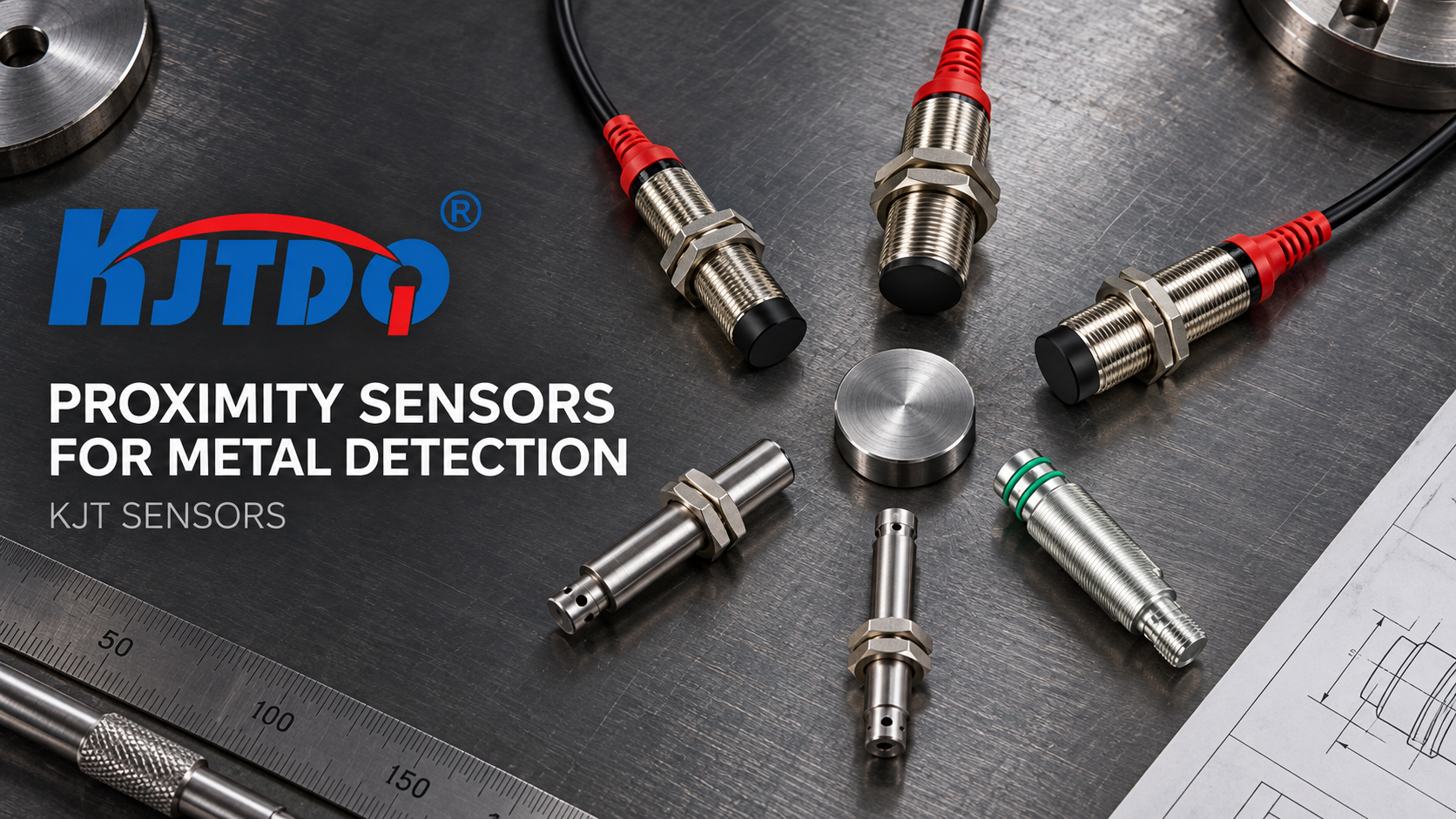
Supply voltage tolerance is one of the least glamorous lines on a proximity sensor specification sheet, and one of the most common causes of intermittent field failures. A sensor that is quoted for a nominal voltage may still misbehave when a real supply sags under load, when rectifier ripple rides on the DC rail, or when a two-wire device is wired into a circuit whose load current was never calculated. Specifying tolerance properly is therefore an engineering exercise, not a purchasing formality. This guide sets out what supply voltage tolerance actually covers, how to specify it in a structured way, and how industrial sensor suppliers such as KJT Sensors approach the question during configuration and quotation.
What Supply Voltage Tolerance Actually Covers
Supply voltage tolerance is the permissible deviation of the actual supply from the sensor’s nominal operating voltage, within which the device is still guaranteed to perform its sensing and switching functions. It is best understood as three separate layers:
The nominal operating voltage is the reference value the sensor is designed around.
The permissible operating band is the window inside which the internal oscillator, signal-processing stage and output stage continue to operate correctly.
The disturbance margin covers everything riding on top of the nominal value: ripple, transients, inrush at start-up, and steady-state voltage drop along the cable.
A specification that names only the nominal figure answers none of these questions. For inductive proximity sensors, the sensing face generates an alternating electromagnetic field; a metal target induces eddy currents and changes the oscillation, which is converted into a switching output. That entire signal chain depends on a stable supply, so tolerance is inseparable from detection accuracy. Capacitive sensors reach the same conclusion by a different route: the sensing face and surrounding environment form a capacitive circuit, and a target changes the dielectric constant and capacitance, which is then processed into a switching signal.
Nominal Voltage Versus the Permissible Band
The first specification decision is the supply class itself. KJT Sensors inductive proximity sensors are available with AC/DC options, and capacitive sensors support switching outputs for connection to a PLC or control circuit. Once the class is fixed, the tolerance question narrows to how far the plant supply is permitted to drift from nominal, and under what conditions that drift is measured.
Two practical distinctions matter here. First, tolerance under no-load conditions tells you very little; the relevant figure is tolerance while the sensor and its downstream load are both drawing current. Second, tolerance is not a single number at a single temperature. Because the sensor’s electronics are specified together with an ambient temperature rating and an IP rating, the effective voltage window should be assessed at the extremes of the installation environment, not on the bench.
A Practical Sequence for Specifying Tolerance
A repeatable sequence keeps the specification defensible:
-
Describe the supply topology. Record whether the machine uses a DC supply, an AC supply, or a mixed arrangement, and how the sensor circuit is fed.
-
Measure rather than assume. Log the minimum and maximum voltage at the sensor connector under real load, including start-up.
-
Select the output configuration. KJT Sensors inductive sensors support NPN or PNP output, two-wire or three-wire wiring, and normally open or normally closed behaviour. Each combination places different demands on the supply.
-
Account for the load path. The sensor output drives a PLC input, a relay, a control cabinet circuit or an automated machine input. The current drawn through the device affects both the usable voltage window and the reliability of the switching signal.
-
Quantify wiring losses. Cable and connector type, run length and connector quality all subtract from the voltage available at the sensing face. Longer runs and small conductor cross-sections consume margin that the tolerance band must absorb.
-
Confirm environmental ratings. Verify the IP rating, temperature rating, and where relevant explosion-protection, corrosion and weld-spatter resistance against the actual site.
-
Document the tolerance in the purchase specification alongside model, housing size and sensing distance, so that the requirement travels with the order.
Where Tolerance Interacts With Product Variants
Voltage tolerance rarely stands alone. In practice it is one of several interlocking requirements that determine which series is appropriate:
-
High-temperature variants exist precisely because a standard proximity switch cannot simply be pushed into a hot process; the supply and switching behaviour must be specified for that temperature class.
-
Explosion-hazardous areas require an intrinsically safe NAMUR product or another suitably certified explosion-proof product, configured in accordance with the site’s explosion-protection requirements. Here voltage tolerance is a compliance matter, not a preference.
-
High-pressure, corrosion-resistant and weld-spatter-resistant variants extend service life where a general-purpose sensor would degrade, and their supply requirements should be confirmed rather than inherited from a standard-model datasheet.
-
Analog-output and wireless variants change the electronics, and therefore change the assumptions behind any tolerance figure taken from a switching model.
-
Ultra-small, ring-type and square designs address confined installations, but compact housings leave less thermal headroom, which makes accurate tolerance specification more important rather than less.
KJT Sensors maintains a broad variant range for exactly these reasons: standard, remote, sanitary, high-pressure, high-temperature, analog output, explosion-proof, full-metal, ultra-small, intrinsically safe NAMUR, corrosion-resistant, ring-type, square, distance, weld-spatter-resistant, wireless and correction factor = 1 series. Mounting options include flush and non-flush installation, and cylindrical, rectangular, ring and flat designs in M8, M12, M18 and other sizes.
Tolerance in Capacitive Applications
Capacitive sensors introduce an additional variable. Because dielectric constants vary by material, field sensitivity is normally adjusted for the material and sensing distance, and that adjustment interacts with stable supply conditions. Applications such as outer-wall liquid-level or powder material-level detection through a non-metallic container wall depend on a stable electric field at the sensing face, so the supply should be verified as part of commissioning rather than treated as a separate electrical concern.
How Quotation Handles Voltage Requirements
Pricing for KJT Sensors inductive proximity sensors reflects product series, housing size, sensing distance, mounting and output configuration, cable or connector type, operating voltage, IP rating, temperature rating, explosion-protection, corrosion and weld-spatter resistance, wireless or analog requirements, order quantity and customization. Capacitive sensors are configured by model, sensing distance, appearance specifications, mounting method, output type, operating voltage, IP rating, sensitivity adjustment method, detection object and site environment.
Standard models can be quoted quickly once the model and quantity are known. Special-environment, import-substitution and non-standard designs require technical review of site conditions, original model specifications, mounting arrangement and control-system interface before quotation — which is where an explicit voltage-tolerance statement saves both parties a round of clarification.
Common Errors to Avoid
Three mistakes recur. The first is selecting PNP or NPN without reference to the PLC input type and field wiring, then discovering that the supply behaves differently than expected. The second is specifying a standard proximity switch for a high-temperature location, where a high-temperature series is required. The third is attempting to use a standard device in an explosion-hazardous area, where an intrinsically safe NAMUR or comparable certified product is required.
Key Takeaways
Supply voltage tolerance should be specified as a band with conditions attached: measured under load, at the temperature extremities of the installation, with the chosen output configuration and wiring accounted for. Treating it as a single nominal figure leaves the tolerance stack unmanaged. Approaching it as part of a structured selection process — supply class, output configuration, load path, wiring, environmental rating and, where applicable, explosion protection — produces a specification that survives contact with the plant floor.
https://www.kjt-sensors.com/
KJT Sensors -
-
AuthorPosts

- You must be logged in to reply to this topic.